
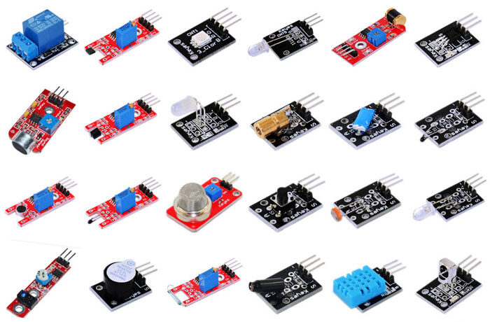
Kit de 37 sensores de Arduino-Raspberry (Ky-005…Ky-0010) Segunda Parte Deja un comentario
Modulos Ky-005 hasta el modulo Ky-010 para Arduino y Raspberry
KY-005: Módulo transmisor de infrarrojos

Descripción:
Es un Led de 5 mm que emite luz infrarroja a 38 khz. Puede venoir o no con una resistencia SMD 103 (10 kΩ).
Tensión de funcionamiento 5V
Corriente directa 30 ~ 60 mA
El consumo de energía 90mW
Temperatura de funcionamiento -25 ° C a 80 ° C [-13 ° F a 176 ° F]
Dimensiones 18.5 mm x 15 mm [0.728 pulgadas x 0.591 pulgadas]
Vf= 1,1V
If= 20mA
Conexión Arduino:


Código Arduino:
#include
Irsend irsend;

void setup()
{
  Serial.begin(9600);
}

void loop()
{
  for(int i = 0; i < 50; i++){
        irsend.sendSony(0xa90, 12);             //Boton power de un TV Sony
        delay(40);

  }
}
Conexión Raspberry:


Desde el Pin VCC del sensor nos conectamos al Colector del transistor NPN 2N2222, de su base a una resistencia de 10kΩ si el módulo no la tuviese(SMD 103) al pin 1 3.3V, el emisor a GND.

Código Raspberry Pi:
Para ver el código funcionando podemos usar la camara del celular para ver el blink, además del led integrado que posee el módulo.
import RPi.GPIO as GPIO
import time

 GPIO.setwarnings(False)
 GPIO.setmode(GPIO.BCM)
 GPIO.setup(17, GPIO.OUT)

 while True:
     GPIO.output(17, True)
     time.sleep(1)
     GPIO.output(17, False)
     time.sleep(1)
Para correr el programa abrimos terminal y tecleamos:
KY-006: Módulo Buzzer-Piezo pasivo

Descripción:
El buzzer pasivo piezo electrico puede generar tonos entre 1.5 y 2.5 Khz, encendiendolo y apagandolo a diferentes frecuencias utilizando delay o PWM.
Conexión Arduino:


Código Arduino:
int buzzer = 8 ;

void setup ()
{
  pinMode (buzzer, OUTPUT) ;
}

void loop ()
{
  unsigned char i;
  while (1)
  {
    //Frequencia 1
    for (i = 0; i <80; i++)
    {
      digitalWrite (buzzer, HIGH) ;
      delay (1) ;
      digitalWrite (buzzer, LOW) ;
      delay (1) ;
    }
    //Frequencia 2
    for (i = 0; i <100; i++)
    {
      digitalWrite (buzzer, HIGH) ;
      delay (2) ;
      digitalWrite (buzzer, LOW) ;
      delay (2) ;
    }
  }
}
Conexión Raspberry Pi:


Código Raspberry Pi:
import RPi.GPIO as GPIO
GPIO.setmode(GPIO.BCM)

GPIO_PIN = 24
GPIO.setup(GPIO_PIN, GPIO.OUT)
Frecuencia = 500         # En Hertz
pwm = GPIO.PWM(GPIO_PIN, Frecuencia)
pwm.start(50)

try:
    while(True):
        print ("----------------------------------------")
        print "Frecuencia actual: %d" % Frecuencia
        Frecuencia = input("Por favor entra una nueva frecuencia entre (50-5000):")
        pwm.ChangeFrequency(Frecuencia)

except KeyboardInterrupt:
    GPIO.cleanup()
Para correr el programa abrimos terminal y tecleamos:
KY-008: Módulo sensor láser

Descripción:
Este módulo tiene integrado un transmisor laser y una interfaz digital, además cuenta
con un LED incorporado.Es el más simple de todos, puede simplemente alimentarse de 3 pilas de 1.5V o 4 de 1.2V. En Raspberry Pi no lleva programación.PRECAUCIÓN no apuntar a los ojos!
Conexión Arduino:


Código Arduino:
int laser = 13;

void setup ()
{
 pinMode (laser, OUTPUT);
}

void loop () {
 digitalWrite (laser, HIGH);
 delay (1000);
 digitalWrite (laser, LOW);
 delay (1000);
}
Conexión Raspberry Pi:


Código Raspberry Pi:
NO SE PROGAMA!
KY-009: Módulo LED RGB SMD

Descripción:
Módulo LED SMD RGB, consiste en un LED capaz de crear cualquier color utilizando RGB, tiene una entrada de voltaje PWM con tres pines. Los colores primarios (rojo / verde / azul) son usados con el fin de lograr el efecto de mezclar colores y obtener cualquier color deseado. Con este módulo se pueden crear efectos de color muy llamativos.
Corriente máxima en el LED: 20mA
Voltaje en cada color: Rojo 1.80V (2.4 max), Verde y Azul 2.8V (3.6V max)
Voltaje de operación: 5V
Vf [Red]= 1,8V
Vf [Green,Blue]= 2,8V
If= 20mA
Resistencias Raspberry Pi:
Rf (3,3V) [Green]= 100Ω
Rf (3,3V) [Red]= 180Ω
Rf (3,3V) [Blue]= 100Ω
Resistencias Arduino:
Rf (5V) [Green] = 100Ω
Rf (5V) [Red] = 180Ω
Rf (5V) [Blue] = 100Ω


Código Arduino:
int Led_Red = 9;
int Led_Green = 10;
int Led_Blue = 11;

int val;

void setup () {
  pinMode (Led_Red, OUTPUT);
  pinMode (Led_Green, OUTPUT);
  pinMode (Led_Blue, OUTPUT);
}
void loop () {

   for (val = 255; val > 0; val--)
      {
       analogWrite (Led_Blue, val);
       analogWrite (Led_Green, 255-val);
       analogWrite (Led_Red, 128-val);
       delay (1);
   }

   for (val = 0; val < 255; val++)
      {
      analogWrite (Led_Blue, val);
      analogWrite (Led_Green, 255-val);
      analogWrite (Led_Red, 128-val);
      delay (1);
   }
}
Conexión Raspberry Pi:


Código Raspberry Pi:
import RPi.GPIO as GPIO
import time

GPIO.setmode(GPIO.BCM)

LED_Red = 22
LED_Green = 24
LED_Blue = 16

GPIO.setup(LED_Red, GPIO.OUT, initial= GPIO.LOW)
GPIO.setup(LED_Green, GPIO.OUT, initial= GPIO.LOW)
GPIO.setup(LED_Blue, GPIO.OUT, initial= GPIO.LOW)

print "LED-Test [press ctrl+c to end]"

# loop
try:
        while True:
            print("LED Red is on for 3 seconds")
            GPIO.output(LED_Red,GPIO.HIGH)
            GPIO.output(LED_Green,GPIO.LOW)
            GPIO.output(LED_Blue,GPIO.LOW)
            time.sleep(3)
            print("LED Green is on for 3 seconds")
            GPIO.output(LED_Red,GPIO.LOW)
            GPIO.output(LED_Green,GPIO.HIGH)
            GPIO.output(LED_Blue,GPIO.LOW)
            time.sleep(3)
            print("LED Blue is on for 3 seconds")
            GPIO.output(LED_Red,GPIO.LOW)
            GPIO.output(LED_Green,GPIO.LOW)
            GPIO.output(LED_Blue,GPIO.HIGH)
            time.sleep(3)

except KeyboardInterrupt:
        GPIO.cleanup()
Para correr el programa abrimos terminal y tecleamos:
KY-010: Módulo barrera óptica

Descripción:
La conexión entre ambos pines de entrada será interrumpida, si la barrera óptica está siendo interrumpida.
Tensión de trabajo 3.3 ~ 5V
Conexión Arduino:


Código Arduino:
int Led = 13;
int Sensor = 10;
int val;

void setup ()
{
  pinMode (Led, OUTPUT) ;
  pinMode (Sensor, INPUT) ;
}

void loop ()
{
  val = digitalRead (Sensor) ;

  if (val == HIGH)
  {
    digitalWrite (Led, HIGH);
  }
  else
  {
    digitalWrite (Led, LOW);
  }
}
Conexión Raspberry Pi:


Código Raspberry Pi:
import RPi.GPIO as GPIO
import time

GPIO.setmode(GPIO.BCM)

GPIO_PIN = 24
GPIO.setup(GPIO_PIN, GPIO.IN, pull_up_down = GPIO.PUD_DOWN)

print "Sensor-Test [press ctrl+c to end the test]"

def outputFunction(null):
        print("Signal detected")

GPIO.add_event_detect(GPIO_PIN, GPIO.RISING, callback=outputFunction, bouncetime=100)

# loop
try:
        while True:
                time.sleep(1)

except KeyboardInterrupt:
        GPIO.cleanup()
Para correr el programa abrimos terminal y tecleamos: